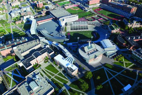
The University of Cincinnati (UC) is a state-supported institution of higher learning and a public research university, founded in the early 1800s and the proud home of the UC Bearcats. The University serves over 47,000 undergraduate and graduate students, including 12,000 employees across the UC campus that spans over 200 acres and is located in the greater Cincinnati metropolitan area. UC operates two central utility plants (east and west) that serve the overall UC campus and also support six area hospitals.

Like many universities across America, The University of Cincinnati had a major challenge having to operate aging central utility plants with older technology, reduced efficiencies and capacities, with chilled water equipment at the end of its service life. Even so, UC needed to maintain plant operations under diverse load conditions, including critical hospital utility demands that are currently expanding and in daily periods subject to energy tariff.

UC’s overall strategy was to develop a multi-year utility plant modernization program, with goals to maximize operational performance, increase efficiencies, recapture lost capacities, reduce peak electric demand and improve operating flexibility through high-performance, oil-free chiller technology and planned optimization strategies.

The critical factors for UC’s chiller solution included:

  • Enhanced operational flexibility
  • Increased central plant efficiency
  • Ability to operate chillers at low loads
  • Expanded redundancy
  • Ease of installation
  • Reduced downtime and maintenance

The University turned to Smardt Chiller Group, the global leader in oil-free, magnetic-bearing centrifugal chillers, and achieved a 32% reduction of kWhr in the new chillers' energy needs compared to the previous unit. This reduction primarily stems from the performance of the chillers’ Danfoss Turbocor® Oil Free Variable Twin Turbo (VTT) compressors that significantly increased production efficiencies and capacities while reducing maintenance costs. The compressors provide enhanced redundancy safeguards and part-load operation while reducing maintenance costs and streamlining management of equipment with a 30+ year service life.

To replace the aging 5,200-ton unit, UC ordered the first two of three Advanced Technology 2,400-ton Magnetic Bearing V Class Chillers from Smardt. The need was particularly urgent because the University’s chiller fleet supplies chilled water to a campus HVAC system that also covers a network of six hospitals and research centers, and any drop in capacity could greatly affect the comfort of patients and personnel – and, most importantly, patient lives.


Subscription users only!

Subscribers are able to view the whole article. Please register/subscribe (it's free and easy) to read all articles.


As businesses embrace environmental initiatives to combat climate change, facility managers and building operators are feeling pressure to increase building efficiency, reduce energy consumption and operating costs. Many are looking to ‘free cooling’ solutions to achieve those goals. Free cooling can take two different forms: air-side economizers that directly exchange cool outdoor air with the building or water-side economizers that use outdoor air to cool the chilled water used to cool the building. This article focuses on water-side economization in particular using two different methods: stand-alone dry coolers and air-cooled chillers with integrated free cooling coils. 

Determining the most effective free cooling strategies requires taking a myriad of factors into consideration. No one scenario may be perfect, but simulations can help reveal which types of buildings and applications are the most likely to benefit. 

There’s a catch, however: These aren’t one-size-fits-all solutions. Free cooling chillers perform differently depending on facility size and location, and effectively applying them into a facility requires understanding the key optimization strategies to make integrated free cooling a viable solution. 


The Rise of the Integrated Water-Side Economizer

Before integral mounting of economizer coils on air-cooled chillers was commonly available, some systems were designed to use separate dry coolers to subject the building heat to the cool outdoor air. Both solutions offer different advantages but making the best choice requires an understanding of the nuances between the two competing designs. 


The Old Way: Stand-Alone Dry Coolers and Chillers

A dry cooler is a stand-alone, fluid-to-air heat exchanger that receives the building cooling loop glycol directly, then exchanges the heat with the outdoor air to cool the loop glycol before returning it to the building or routing through the chiller. In warmer ambient conditions where the dry cooler is unable to cool the fluid completely, the fluid flows through the chiller to receive supplemental mechanical cooling. To control the fluid flow path, the three-way valves connecting the building cooling water loop to the chiller and fluid cooler open or close, allowing the flow to bypass the dry cooler or chiller when appropriate, which helps manage pressure drop.


The New Way: Integrated Free Cooling

Similar in concept to a dry cooler, integrated free cooling uses glycol to air coils, but unlike dry coolers, these coils are typically attached to the chiller on the outside of the primary condenser coil to cool the process fluid using low temperature ambient air. Integrated free cooling chillers typically operate in one of three “modes.” 

In mechanical cooling mode, the unit functions just like a normal air-cooled chiller, cooling the glycol using the refrigeration cycle. This is done when the ambient temperature is above the leaving glycol temperature. 

In hybrid mode, glycol is diverted first through the air coils where it is partially cooled, and then diverted into the evaporator where it is further cooled to meet the design fluid temperature setpoint. Hybrid mode is used when the ambient temperature is below the entering fluid temperature, but not low enough to achieve 100 percent free cooling. 

Because hybrid mode operates in mild ambient temperatures, it can often represent the greatest number of run hours. This means optimizing operation during hybrid mode is crucial for maximizing system efficiency and achieving the best return on investment.


Subscription users only!

Subscribers are able to view the whole article. Please register/subscribe (it's free and easy) to read all articles.


Overview

Water-cooled chiller plants have three major components that consume electricity: the chiller, the condenser and evaporator pumps, and the cooling tower fan. The chiller consumes the highest amount of total plant room energy. In certain applications, the energy consumption of a chiller is very significant. For example, in district energy applications, chillers may consume more than 75 percent of the facility’s total energy.

For the designers, owners, and operators of chiller plants, it is important to understand what causes a chiller to consume power and what strategies can be implemented to optimize power consumption during high loads. This is particularly true for district cooling plants, where chillers generally operate at higher loads to achieve their objectives.

It is important to establish the metrics to accurately illustrate the correct way to optimize the efficiency of chilled water systems. These metrics inform all recommendations about the evaluation of the impact of off-design operation.

A common misconception in chiller performance evaluation is that design full-load kW/Ton is directly indicative of chiller efficiency. Reducing the chiller selection process to full-load efficiency does not account for a more representative and impactful metric: off-design energy efficiency or annual energy efficiency.

If owners and operators of chiller plants only consider full loads, it can result in unexpected energy use consequences. One of the best ways to improve annual efficiency levels is to employ a VSD for the chiller compressor motor. VSDs are powered devices, which means they negatively impact the full-load performance of chillers, but they are an excellent way to reduce operating costs and improve annual efficiency.

VSDs reduce the energy consumption of chillers, especially compared to CSDs, even in applications where chillers run at continuously high loads. To prove this, a new metric is proposed. This metric is a more accurate alignment of specific power input to expected annual energy consumption.

The validity of the newly proposed metric is corroborated by the case study presented in this paper. Finally, this paper does not address the electrical design and topology of a VSD, but rather a VSD’s impact on the compressor of a chiller and - by extension - overall energy performance.

Figure 1


VSD Impact on Chiller Power Consumption

System designers will specify that a chiller be designed to operate at the most severe condition (the design condition) to avoid insufficient cooling on the most important days. The design condition is used to calculate the maximum instantaneous power consumption. This is then used to size critical electrical components, such as circuit breakers, wires, and generators.

However, chillers run at design conditions for less than 10 percent of the year. Therefore, off-design performance is more important to the overall evaluation of a chilled water system. This is particularly true for applications where chillers run at high loads throughout the year – for example, plant rooms in data centers and other facilities that require process cooling. In these facilities, the chilling duty does not change.

A water-cooled chiller’s instantaneous power consumption varies because of two dynamics. The first is the variation in the capacity required by the system, and the second is the amount of compression required. This is illustrated in Figure 2.


Subscription users only!

Subscribers are able to view the whole article. Please register/subscribe (it's free and easy) to read all articles.


Berry Global was established in 1967 as a small hometown company, based in Evansville, Indiana. Today it is still headquartered in Evansville but has grown to 48,000+ global employees and more than 295 locations. Generating $12.6 billion in 2019 pro forma net sales, Berry Global creates innovative packaging and protection solutions.

Berry Global is a company which has grown through many acquisitions and now operate around 120 manufacturing sites in the U.S. Berry Global has over fifteen unique different plastic production processes. The processes will vary from plant-to-plant and, to name a few, include injection molding, blow molding, cast film, and blown film.

In February 2021, Chiller & Cooling and Compressed Air Best Practices Magazines interviewed members of the Berry Global Corporate Plant Engineering Team to gain an understanding of the work being done to improve system reliability and energy efficiency. The team members interviewed were Chris Tedford (Director of Corporate Plant Engineering), Daniel K. Pemberton (Corporate Project Engineer), and Tyler W. Lyons (Corporate Plant Engineering Manager).


Chris, what is the mission of the corporate engineering team at Berry Global?

We’ve had a Corporate Plant Engineering team for some time now and our primary objective is to help improve the reliability and efficiency of our manufacturing plant infrastructure and plant utilities. This means we cover a lot of ground including chilled water (cooling) systems, water treatment, compressed air, resin conveying systems, lighting, and electrical system safety and reliability. In our organization, some projects are plant led, where others require a very hands on approach with lots of onsite project management and some projects where we mainly help with the initial scoping and justification to get it ready for capital approval.

The team is working to develop subject matter experts in key areas. Daniel Pemberton focuses on compressed air systems and Tyler Lyons focuses on chillers, cooling towers, and cooling systems in general.

Having grown by acquisition, we are well accustomed to the discovery process of bringing a new facility into our organization. Over time our plants have taken different approaches on how to expand their infrastructure systems to meet the needs of plant expansions. Many of the plants have added equipment to meet the needs of production, which has led to poorly optimized systems. Trying to drive consistency across our plants is a challenge we have taken on. Our team has done a great job of creating a centralized inventory of assets and using that to identify, prioritize, develop, and ultimately execute on these opportunities.


An air compressor room with single-stage rotary screw air compressors and refrigerated compressed air dryers.


Daniel, Can you describe the work being done with compressed air systems?

Compressed air is a relatively new initiative, at the corporate level. The plants obviously have been managing compressed air for a long time.


Subscription users only!

Subscribers are able to view the whole article. Please register/subscribe (it's free and easy) to read all articles.


The inefficiency of fossil fuels, along with the negative environmental impact coming from their burning and resulting emissions, is driving companies to find alternative heating and cooling solutions. While renewable sources – such as wind and solar power – are decreasing this impact, other fossil fuel-burning sources need to be replaced with electric-driven alternatives to fully realize their emissions reduction potential. New vapor compression technology can help reduce heating and cooling operations while providing these additional CO2 emissions reductions.

Air-to-water heat pumps provide much more efficient heating compared to fossil fuel-sourced solutions. They are approximately 3.5 times more efficient than boilers, before accounting for the transmission and distribution losses. Even with the inefficiencies of the power generation needed to fuel electric heat pumps, there is still an opportunity for this air-to-water heat pump to realize about 35% operating cost reduction, as well as 60% emissions reduction.

Recent heat pump vapor compression innovations are much more efficient – particularly at part-load operation – whereas boilers and furnaces do not see significant additional efficiencies at part-load conditions. The goal of eliminating CO2 emissions requires a reduction in energy consumption and the decarbonization of the energy consumed, while finding alternatives to inefficient fossil fuel-fired heating sources. By nature, heat pumps – and especially these more recent innovations – are intended to optimize energy for both cooling and heating at those varying operating conditions.


U.S. Clean Energy Commitments

As U.S. federal climate policies and strategies continue to evolve, efforts from individual states are already underway to implement a significant increase of renewable energy sources. According to the World Resources Institute, in 2019, multiple states committed to a 100% renewable energy source. Deadlines for reaching these goals ranged from 2035 to 2050.

However, the reality must match the commitment. To this end, 76% of all 2020 new US planned power generation capacity is either wind or solar. Additionally, the IEA in November 2020 provided an update that, globally, renewables constituted 90% of this year’s new installed power generation. As the nation transitions to renewables, there will always be a need for some level of backup, since these natural resources are at the mercy of the environment. These backups – historically known as peaking plants – are necessary when the demand side is high and there are renewable source deficiencies. These constitute the remaining 24% of new 2020 planned generation capacity. Significant growth in the percentage of renewables in the electric power generation portfolio is driving the need for heat pumps that are replacing fossil fuel-based sources and driving an additional increase in the decarbonization potential.


Subscription users only!

Subscribers are able to view the whole article. Please register/subscribe (it's free and easy) to read all articles.


With efficient heat exchange an important requirement in the design of an HVAC system, the type of cooling tower you specify to support your project’s unique cooling goals requires careful consideration. After determining the process parameters required for your application – tonnage, range, and approach – cooling tower capabilities can be analyzed.

crossflow (left) and counterflow (right)

Choosing between crossflow (left) and counterflow (right) cooling towers for your application depends on the factors most important to your project specifications.

Because induced draft crossflow and counterflow cooling towers both have distinct advantages, the design requirements and conditions specific to your application determine the appropriate cooling tower for your project. The fundamental difference between crossflow and counterflow cooling towers is how the air moving through the tower interacts with the process water being cooled. In a crossflow tower, air travels horizontally across the direction of the falling water. In a counterflow tower, air travels vertically upwards in the opposite direction (counter) to the direction of the falling water.

While structural and mechanical components of crossflow and counterflow cooling towers are similar, application-specific design requirements should determine the tower type.

The fundamental difference between crossflow and counterflow cooling towers is how the air moving through the cooling tower interacts with the process water being cooled. Air travels horizontally across the direction of the falling water in a crossflow tower. In a counterflow tower air travels vertically upwards in the opposite direction (counter) to the falling water.


Physical Size - Footprint

Every cooling tower requires a certain volume of air to effectively exchange the heat in the process water. Thus, a cooling tower’s plan area and height must be considered with your specific application in mind.

At cooling capacities up to about 750 tons (3295kW), a counterflow cooling tower with its vertically-stacked components may require less plan area than a crossflow cooling tower. Beyond the 750 ton mark, because crossflow tower modules are stacked vertically at higher tonnages, a counterflow tower offers little to no advantage in footprint versus a crossflow tower and can sometimes take up more plan area.

Depending on the application, a crossflow cooling tower may require less total area than a counterflow tower even at heat loads less than 750 tons because of the location and number of air inlets – a crossflow tower has two air inlets compared to four air inlets on a counterflow tower.


Subscription users only!

Subscribers are able to view the whole article. Please register/subscribe (it's free and easy) to read all articles.


Over decades, a well-known plastics extruder in the Midwest built a solid reputation for delivering high quality, high-performance polymers – which in turn – allowed its customers to produce products on time and on budget. The company’s reputation is based not only on a proven track record, but in making sound investments in plant operations, such as the decision to overhaul its process cooling system when the time was right. 

By replacing chillers nearing their end of life with chillers from Chase Cooling Systems, the company has kept pace with increased production and a growing list of satisfied customers. 

To keep pace with continued growth and eliminate maintenance issues with existing chillers nearing their end of life, a plastics extruder in the Midwest upgraded its central chiller plant with chillers from Chase Cooling Systems.


A Leader in High-performance Polymers 

At the company’s production plant employees manufacture a complete range of engineered, high-performance polymers. At the heart of the operation are numerous extrusion lines and related equipment that operate 24 hours a day, five days per week to produce and ship as much as five million pounds of high-performance polymer pellets each month. 

The process of producing pellets begins when the rotating screw on each extruder accepts a carefully calibrated mix of thermoplastic materials, as well as additives, from a hopper and pushes the mixture into the extruder’s barrel. Inside the barrel, material is heated and cooled to the proper melt temperature, which ranges from 400 to 500 oF depending on the materials involved. The screw then forces the material through a die to create a continuous strand of plastic resin, which is then cooled as it travels through a water bath. At the opposite end of the extrusion line, the strands of resin are dried and cut into pellets for shipment.


Cooling Temperatures Vital to Extrusion Process

Chilled water supplied to the extrusion lines is vital to production and product quality goals. Yet the aging central chiller plant was unable to keep pace with demand for chilled water and experienced maintenance issues, which led to plans for a chiller system upgrade. 

The original chiller plant system featured four air-cooled chillers used to supply chilled water at 45 oF to the extruders and other production equipment. Three of the original chillers, with a cooling capacity of 30 tons each, were located outside the facility. The system also included a fourth chiller, rated to provide 160 tons of cooling. The fourth unit is a split-system with the evaporator installed inside the plant and the condensing unit, which includes the compressor, condenser, and fans, located outside the building. In all, the original chiller plant system provided approximately 250 tons of cooling capacity. 

The chiller system also features a cold- and warm-water tank, each of which has a capacity of 3,000 gallons. The system’s two Variable Speed Drive (VFD) pumps feed warm water from the warm water tank to the chillers at 700 gallons per minute (gpm) and 30 pounds per square inch (psi). The system also includes two separate process pumps to supply chilled water from the cold water tank to production areas at 1,500 gpm and 40 psi. 


Subscription users only!

Subscribers are able to view the whole article. Please register/subscribe (it's free and easy) to read all articles.


01/12/2015

Blower and Vacuum Logo

Thank you for your interest in Blower & Vacuum Best Practices.

Digital subscriptions are free worldwide. Print subscriptions are free in the USA.